| |
| T H E S P A C
E |
| Since the only pictorial input into
this installation is its immediate surroundings
as seen by the cameras, the choice of space assumes
a critical role. Odd spaces of intersecting corridors,
staircases, corners with horizontal, vertical,
or diagonal shapes and shadows are an ideal backdrop
for the observer approaching the exhibit. When
only a featureless room is offered, Steina includes
large vertical photo panels by Woody Vasulka to
be mounted on the walls to provide a graphic backdrop.
Machine Vision (and Allvision) are the only
works of Steina’s requiring daylight or
a fair amount of artificial illumination. They
are closed-circuit environments with no additional
media on tape or disk. There is no audio present. |
|
| |
| E Q U I P M E N T |
| The Vasulkas can provide all the
equipment listed below, or share resources with
the exhibitor. This will be reflected in both
shipping and equipment budgets. |
|
| 1. ALLVISION
(see separate description) |
|
| 2.
Rotation: A camera fitted with a motorized prism
lens provides a continuous rotation. |
3. Zoom:
A camera fitted with a motorized zoom lens provides
a continuous in/out zoom. |
| |
video
camera
motorized prism lens
power supply (12 VDC)
power supply (3 VDC)
tripod
video cable to monitor
power cable |
|
video
camera
motorized zoom lens
power supply (3 VDC)
power supply (12 VDC)
power supply (12 VDC)
tripod
video cable to monitor
power cable |
|
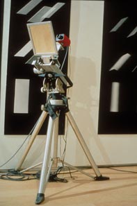
| 4.
Pan: A moving mirror assembly placed in front
of the camera provides a continuous pan, back
and forth. |
5. Tilt:
A moving mirror assembly placed in front of the
camera provides a continuous tilt, up and down. |
| |
video
camera
motorized mirror assembly
power supply (12 VDC)
power supply (12 VDC)
tripod
video cable to monitor
power cable |
|
video
camera
motorized mirror assembly
power supply (12 VDC)
power supply (12 VDC)
tripod
video cable to monitor
power cable |
|
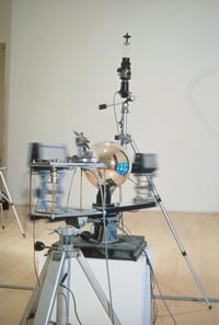
| 6.
Double Rotation (slant mirror): A vertically placed
camera points into a rotating slanted mirror,
resulting in a rotation on two axis, horizontal
and vertical. |
7. Bird’s-Eye:
A vertically placed camera is fitted with a motorized
prism lens and a small mir-rored sphere providing
a continuous rotation. |
| |
video
camera
motorized mirror assembly
power supply (12 VDC)
power supply (3 VDC)
tripod
video cable to monitor
power cable |
|
video
camera
motorized prism lens
power supply (12 VDC)
power supply (3 VDC)
tripod
video cable to monitor
power cable |
|
SUMMARY OF EQUIPMENT |
|
| |
8
b/w video cameras
15 powersupplies
2 moving mirror assemblies
2 prizm lenses
1 birds-eye lens
1 zoom lens
1 slant mirror
7 tripods |
NOTE: These mini installations
come pre-assembled. They need only to be mounted
on tripods and arranged in space. There are 8
video cables from each installation to the monitors. |
|
| |
| M O N I T O R M
A T R I X A N D P L A
T F O R MS |
| The placement of the monitors is
determined by the size of the monitors and the
space itself. A matrix of 12 monitors, 3 x 4 is
recommended. The following diagram shows the wiring
sequence for 12 monitors. |
|
| |
 |
| |
| T H E D I S P
L A Y |
| By selecting more sensitive cameras,
the general light level in the environment could
be kept low and the balance of light could tip
in favor of stronger display image. The monitors
should therefore not be exposed to direct light.
The space should be flooded in all directions
either by artificial or natural light. It is important
that the environment reflected in the sphere exhibits
great variety of forms and architectural features,
contrast in color and brightness. The dynamic
additions to the environment are the viewers. |
|
| |
| V I D E O A D
J U S T M E N T |
| All 75 ohm terminators located on
the back of the monitors must be switched to open,
except for the last monitor on each chain. Contrast
should be high and brightness below middle. The
basic rule here is to set up the proper deep color
black as a reference to the maximum contrast and
brightness. With that, the other components (hue,
color saturation) can be assigned. The persons
installing the environment must use their esthetic
judgment as to the proper monitor settings for
maximum visual impact. |
|
| |
| D A I L Y O P
E R A T I O N S |
TO START:
Power up the monitors, cameras and motors at each
station. Verify that each installation goes into
motion and displays video on the monitors. If
not, turn power off and on again. If problem persists
notify Steina by phone, fax or e-mail.
TO SHUT DOWN:
Power down monitors, cameras, and motor assemblies.
MAINTENANCE:
Power down monitors, cameras, and motor assemblies. |
|
| |
| P O W E R R
E Q U I R E M E N T S |
| |
Video
monitors (12)
VDC Power Supplies (15)
Turntable |
Sony
PWM 1910
15 VDC |
120
watts
5 watts
40 watts |
|
| NOTE: All power supplies
for Machine Vision are dual standard, 110 to 220
VAC. Video: PAL/NTSC (cameras/monitors of a matching
standard). |
|
| |
| L I S T
O F P O W E R S U P P L I E
S |
| |
1. Allvision
2.Rotation I
3. Zoom
4. Pan
5. Tilt
6. Slant Mirror
7. Rotation II |
12 VDC + 12 VDC
12 VDC + 3VDC
12 VDC + 3 VDC + 12VDC
12 VDC + 12 VDC
12 VDC + 12 VDC
12 VDC + 05VDC
12 VDC + 03 VDC |
|
|
| |
| C R E D I T S |
At the entrance these credits should
appear:
“Machine Vision by Steina, with
instrumentation by Josef Krames, Woody Vasulka,
and Bruce Hamilton.” |
|
| |
| S H I P P I N G
I N F O R M A T I O N |
| Installation is shipped in four
crates. Weight and dimensions available upon request. |
|
| |